 RW
Info:
RW
Info:
CALIBRATING / CONTROLLING
REPRODUCTION
AND PRECISION QUALITY OF YOUR CtP IMAGE/PLATESETTER'S UNDER ISO 12218:
The number of computer-to-plate imagesetters
installed almost
doubles every year. However,
the new technology also involves several risks. Conventional
plate production has been used for years and the processes and controls
are continuously improved. With
the
new CtP technology, the high sensitivity of the plates requires a more
exact quality control, involving
in
part, the use of different control instruments. In principle, a
distinction
must be made between the different
types of plates.
This means not only making a distinction between the various processes, such as silver, photopolymer and thermophotopolymer, but also taking into account the fact that technical recommendations differ from one plate manufacturer to another. The example of a photopolymer plate will be taken here to describe the determination of the laser intensity. We wish to point out that the following recommendations only represent summarized basic information and that it is essential to heed the information and recommendations of the manufacturers.
.
Laser intensity
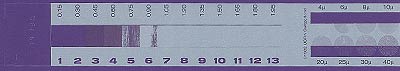
Laser power diminishes with age. In addition, as a result of different production conditions (e.g. chemical composition), plates can have slightly different degrees of sensitivity. For both of these reasons, the laser exposure intensity on the plate should be checked, for example, whether the exposure is sufficient to ensure that the plate survives a suitable number of impressions. The method for the photopolymer plate is the use of an analog filter, or control wedge respectively, such as is contained in the Ugra 82/95 test wedge. In the United States, the Stouffer wedge is frequently used.
To use the Ugra 82/95 Offset test wedge (applies only for photopolymer plate), tape the control wedge to a plate under light-protected conditions. Position the first wedge in the middle of the plate, the second at the edge (leading or trailing). Completely expose the plate (a special function in the imagesetter) or expose a totally black page. Remove the control wedge under light-protected conditions before development. Return the plate to the imagesetter and carry out development. Patches two and three should be completely covered and there should be no difference in color and gloss. This is best determined by the reflection of the surface. Patch four should show a difference.
When should the test take place?
Ideally, daily before production and on every imagesetter. Otherwise, at least twice weekly on every imagesetter before production. Also test after every plate batch change (see plate packaging) and after every change of chemicals. Care should be taken to ensure the imagesetter and developing machine have reached the necessary working temperature.
.
"Gray plate"
As a next step, it should be verified that the plate is exposed and developed in a uniform manner. This test should be carried out for all plates. Expose a page that is covered completely with a 50-percent dot area screen. Check the screen ruling and dot sizes with the aid of control devices, such as a
Techkon SpectroPlate (digital microscope),
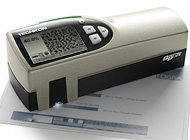
Centurfax ccDot 5 or GretagMacbeth
IC-Plate.
Ideally, the values should be identical at all positions.
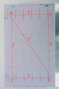
On the basis of a
special test
page, the plate
can be measured using a high-precision
electronic ruler.
.
Depending on the manufacturers data supplied in the specifications or offer, different tolerances may be possible. Fluctuations are not always exclusively because of the imagesetter. In exceptional cases, the plate properties and the developing machine can cause fluctuations. Carrying out a second test can at least eliminate the possibility of a fluctuation being due to the plate properties.
If the plate is turned
180 degrees
before entry into the developing machine, it may be possible to exclude
any influence of the developer in the
fluctuations.
Most imagesetters expose two plates in different positions
on the exposure table or in the drum of the imagesetter. Both positions
must be checked. This test should
be
carried out weekly for every imagesetter.
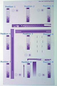
The gradation patches
should
be measured
in a total of nine positions.
.
With photopolymer plates
it is
also possible to check whether streaks or stripes are visible. Such
stripes
are an indication of insufficient
brush
pressure in the developing machine. If that is the case, we recommend
you have a qualified specialist or a
technician
from the manufacturer adjust the brush pressure in the developing
machine.
.
 .
.
The Ugra control wedge provides information about the hardening of the Agfa N91 plate.
..
Test with nine control wedges
In this test, a page is exposed with a total of nine control wedges distributed equally on the plate.
The test can have two objectives:
1
PRECISION
To determine the laser precision across the full exposure surface. In this case, the exposure consistency in all nine control wedges is checked. The main aim here is to check the possible deviations of an imagesetter, or between several image-setters. It is possible that an imagesetter supplies relatively uniform values in the 50-percent dot area patches in all areas of the plate, but shows considerable deviations e.g. in the 10-percent dot area patches. For the purpose of this analysis, the calibration of the exposure is of no consequence.
If two imagesetters produce results that differ greatly from one another, then the technician must intervene. For an in-depth test, e.g. acceptance testing equipment, all patches should be measured. For control tests carried out at regular intervals, e.g. every two weeks, far fewer patches will be sufficient, e.g. 2, 5, 10, 20, 40, 50, 60 and 90. Here also, in case of strongly deviating values, it is necessary to repeat the test to eliminate any fluctuation in the properties of the test plate.
2
CALIBRATION
In the case of uncalibrated exposure, this test can be used to calculate a matching curve for the raster image processor to compensate for the dot gain of the plate (positive plates, e.g. Agfa N91, Fuji LPN-N and Kodak Thermo). The curve should result from measurements of all the imagesetters and plate positions. All measurement patches should be evaluated for this. The measured values are usually entered into a table in the RIP. The RIP then calculates a transfer curve. All according and respecting ISO 12218 recomended values.
The calibration should be carried out in such a way that the 50-percent dot area patch of the data file is measured as 50-percent dot area on the plate. Strictly speaking, according to ISO 12647, a target value of 53 percent measured on the plate should be achieved to obtain the same value as in negative platemaking. But the problem is that the values are usually difficult to apply to the calibration curve of a RIP.
Anyone using CTP plates and conventional plates should also run a printing test and compare the dot gain of the different plate types. Some CTP plates print sharper than conventional plates, but it is impossible to define general rules or give recommendations. The aforementioned tests must be carried out for all. In addition to the nine gradation measuring patches, it is also possible to expose a star target in different positions on the plate. In writing the center of the star target, the shape of the laser beam is accurately portrayed in a magnified form. For example, it is possible to detect an elliptical distortion in certain positions.
A test page with a fine line pattern is exposed and measured. For this, a high-precision electronic ruler is necessary. It is also possible to carry out a double exposure when comparing two plate positions to make any differences visible.
In cases where optical punching systems that work with video techniques are used, such a verification is usually not necessary because the system announces possible deviations and ejects the plate unpunched. With three-point lay systems with optical control, this test can still be necessary. Also, it can be used to check areas situated outside the register marks. Therefore, it is possible, for example, to detect an image distortion at the plate edge that is not recorded by the video cameras of the punching system.
.
Control elements on every plate
To continually control daily production, control elements should be attached to the edge area of each plate. Especially suitable for this purpose are the control wedges of the plate manufacturers, e.g. DigiControl from Agfa for the N91, or other control wedges that include halftone screen patches and e.g. microlines. With the aid of these control wedges, it is possible, even by a purely visual control, to discover a fault in the plate production process.
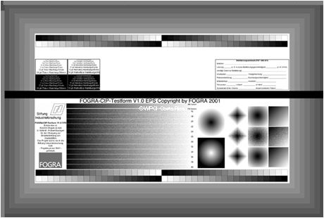
FOGRA CtP Control Element
We also recomend the use of the FOGRA CtP Test Element to confirm CtP reproduction and precision quality:
Based on the above proposals, I'm offering CtP acceptance and quality tests according ISO, FOGRA, GATF IFRA recomendations for your sistem!
ing. rainer wagner:
YES, we will help and assist YOU in calibrating, controlling and certifying your platesetter equipment!
Please contact:
.
EXPERIENCE IS OUR EXPERTISE!
© 2022 Copyright by rainer wagner